TMAQ67LABC-11A | E14R00P38
Quad-pack Tower Mounted Amplifier 600/700 MHz,4.3-10
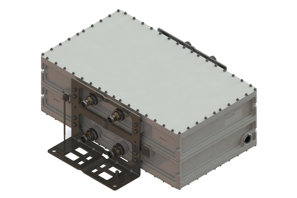
Features and benefits
- Variable gain, in steps of 1 dB
- New 4.3-10 connectors for improved PIM performance and size reduction
Specifications
Product classification
| Product Type | Tower mounted amplifier |
General specifications
| Color | Gray |
| Modularity | 4-Quad |
| RF Connector Interface | 4.3-10 Female |
| RF Connector Interface Body Style | Long neck |
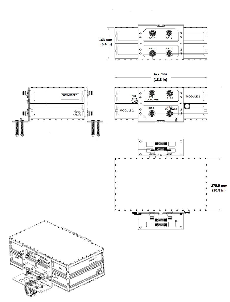
Dimensions
| Height | 477 mm | 18.78 in |
| Width | 275.5 mm | 10.846 in |
| Depth | 163 mm | 6.417 in |
Outline drawing
| Click on image to enlarge. |
Electrical specifications
| License Band, LNA | USA 700 | USA 750 |
Electrical specifications, dc power/alarm
| Lightning Surge Current | 10 kA |
| Lightning Surge Current Waveform | 8/20 waveform |
Electrical specifications, aisg
| AISG Carrier | 2.176 MHz ± 100 ppm |
| AISG Connector | 8-pin DIN Female |
| AISG Connector Standard | IEC 60130-9 |
| Protocol | AISG 2.0 |
| Voltage, AISG Mode | 10–30 Vdc |
Electrical specifications
| Sub-module | 1 | 2 | 3 | 4 | 1 | 2 | 3 | 4 |
| Branch | 1 | 1 |
| AISG 2.0 Device Subunit | E14R00P38 1/3/5/7 | E14R00P38 2/4/6/8 |
| License Band | USA 700, LNA |
Electrical specifications, rx uplink
| Frequency Range, MHz | 663–698 | 698–716 |
| Gain, nominal, dB | 13.0 | 13.0 |
| Gain Tolerance, dB | ±1.3 | ±1.3 |
| Gain Adjustment Range, dB | 5-13 | 5-13 |
| Gain Adjustment Range Increments, dB | 1 | 1 |
| Noise Figure, typical, dB | 1.2 | 1.2 |
| Group Delay Variation, maximum, ns | 8 | 8 |
| Group Delay Variation Bandwidth, MHz | 0.18 | 0.18 |
| Total Group Delay, maximum, ns | 250 | 250 |
| Return Loss, typical, dB | 22 | 22 |
| Insertion Loss - Bypass Mode, typical, dB | 2.0 | 2.0 |
| Return Loss - Bypass Mode, typical, dB | 16 | 16 |
Electrical specifications, tx downlink
| Frequency Range, MHz | 617–652 | 728–746 |
| Insertion Loss, typical, dB | 0.30 | 0.30 |
| Total Group Delay, maximum, ns | 70 | 70 |
| Return Loss, typical, dB | 22 | 22 |
| Input Power, RMS, maximum, W | 200 | 200 |
| Input Power, PEP, maximum, W | 2,000 | 2,000 |
| 3rd Order PIM, typical, dBc | -155 | -155 |
| 3rd Order PIM Test Method | 2 x 20 W CW tones | 2 x 20 W CW tones |
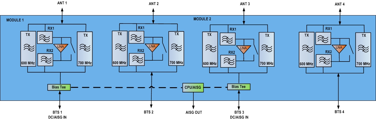
Block diagram
| Click on image to enlarge. |
Material specifications
| Finish | Painted |
Environmental specifications
| Operating Temperature | -40 °C to +65 °C (-40 °F to +149 °F) |
| Relative Humidity | Up to 100% |
| Corrosion Test Method | IEC 60068-2-11, 30 days |
| Ingress Protection Test Method | IEC 60529:2001, IP67 |
Packaging and weights
| Mounting Hardware Weight | 2 kg | 4.409 lb |
| Weight, without mounting hardware | 23.8 kg | 52.47 lb |
Product classification
| Product Type | Tower mounted amplifier |
General specifications
| Color | Gray |
| Modularity | 4-Quad |
| RF Connector Interface | 4.3-10 Female |
| RF Connector Interface Body Style | Long neck |
Dimensions
| Height | 477 mm | 18.78 in |
| Width | 275.5 mm | 10.846 in |
| Depth | 163 mm | 6.417 in |
Electrical specifications
| License Band, LNA | USA 700 | USA 750 |
Electrical specifications, dc power/alarm
| Lightning Surge Current | 10 kA |
| Lightning Surge Current Waveform | 8/20 waveform |
Electrical specifications, aisg
| AISG Carrier | 2.176 MHz ± 100 ppm |
| AISG Connector | 8-pin DIN Female |
| AISG Connector Standard | IEC 60130-9 |
| Protocol | AISG 2.0 |
| Voltage, AISG Mode | 10–30 Vdc |
Electrical specifications
| Sub-module | 1 | 2 | 3 | 4 | 1 | 2 | 3 | 4 |
| Branch | 1 | 1 |
| AISG 2.0 Device Subunit | E14R00P38 1/3/5/7 | E14R00P38 2/4/6/8 |
| License Band | USA 700, LNA |
Electrical specifications, rx uplink
| Frequency Range, MHz | 663–698 | 698–716 |
| Gain, nominal, dB | 13.0 | 13.0 |
| Gain Tolerance, dB | ±1.3 | ±1.3 |
| Gain Adjustment Range, dB | 5-13 | 5-13 |
| Gain Adjustment Range Increments, dB | 1 | 1 |
| Noise Figure, typical, dB | 1.2 | 1.2 |
| Group Delay Variation, maximum, ns | 8 | 8 |
| Group Delay Variation Bandwidth, MHz | 0.18 | 0.18 |
| Total Group Delay, maximum, ns | 250 | 250 |
| Return Loss, typical, dB | 22 | 22 |
| Insertion Loss - Bypass Mode, typical, dB | 2.0 | 2.0 |
| Return Loss - Bypass Mode, typical, dB | 16 | 16 |
Electrical specifications, tx downlink
| Frequency Range, MHz | 617–652 | 728–746 |
| Insertion Loss, typical, dB | 0.30 | 0.30 |
| Total Group Delay, maximum, ns | 70 | 70 |
| Return Loss, typical, dB | 22 | 22 |
| Input Power, RMS, maximum, W | 200 | 200 |
| Input Power, PEP, maximum, W | 2,000 | 2,000 |
| 3rd Order PIM, typical, dBc | -155 | -155 |
| 3rd Order PIM Test Method | 2 x 20 W CW tones | 2 x 20 W CW tones |
Material specifications
| Finish | Painted |
Environmental specifications
| Operating Temperature | -40 °C to +65 °C (-40 °F to +149 °F) |
| Relative Humidity | Up to 100% |
| Corrosion Test Method | IEC 60068-2-11, 30 days |
| Ingress Protection Test Method | IEC 60529:2001, IP67 |
Packaging and weights
| Mounting Hardware Weight | 2 kg | 4.409 lb |
| Weight, without mounting hardware | 23.8 kg | 52.47 lb |
| Click on image to enlarge. |
| Click on image to enlarge. |
Installation & videos
Installation instruction
Filter Products – Designed for PIM Excellence

Filter Products – Designed for PIM Excellence
Documentation & downloads